
TrussFormer: 3D printing large kinetic structures
Robert Kovacs, Alexandra Ion, Pedro Lopes, Tim Oesterreich, Johannes Filter, Philip Otto, Tobias Arndt, Nico Ring, Melvin Witte, Anton Synytsia, and Patrick Baudisch
In Proceedings of the 31th Annual ACM Symposium on User Interface Software and Technology (UIST ’18)
paper: PDF
ACM Digital Library
TrussFormer is an integrated end-to-end system that allows users to 3D print large-scale kinetic structures, i.e., structures that involve motion and deal with dynamic forces.
TrussFormer builds on TrussFab, from which it inherits the ability to create large-scale static truss structures from 3D printed hubs and PET bottles.
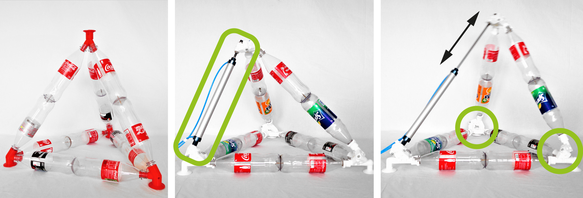
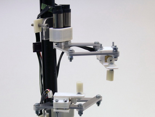
TrussFormer incorporates linear actuators into these rigid truss structures in a way that they move “organically”, i.e., hinge around multiple points at the same time. These structures are also known as variable geometry trusses. This is illustrated on the on the example of a static tetrahedron that is converted into a moving structure by swapping one edge with a linear actuator. The only required change is to introduce connectors that enable rotation, i.e. hinges.
![]()
Robert Kovacs, Alexandra Ion, Pedro Lopes, Tim Oesterreich, Johannes Filter, Philip Otto, Tobias Arndt, Nico Ring, Melvin Witte, Anton Synytsia, and Patrick Baudisch
In Proceedings of the 31th Annual ACM Symposium on User Interface Software and Technology (UIST ’18)
paper: PDF
ACM Digital Library
TrussFormer is an integrated end-to-end system that allows users to 3D print large-scale kinetic structures, i.e., structures that involve motion and deal with dynamic forces.
TrussFormer builds on TrussFab, from which it inherits the ability to create large-scale static truss structures from 3D printed hubs and PET bottles.
TrussFormer incorporates linear actuators into these rigid truss structures in a way that they move “organically”, i.e., hinge around multiple points at the same time. These structures are also known as variable geometry trusses. This is illustrated on the on the example of a static tetrahedron that is converted into a moving structure by swapping one edge with a linear actuator. The only required change is to introduce connectors that enable rotation, i.e. hinges.
TrussFormer creates these mechanisms in six basic steps:
step 1: Creating the static structure. TrussFormer's editor’s ability to create static structures is based on TrussFab: users design the shape of their T-Rex using structurally stable primitives (tetrahedra and octahedra).
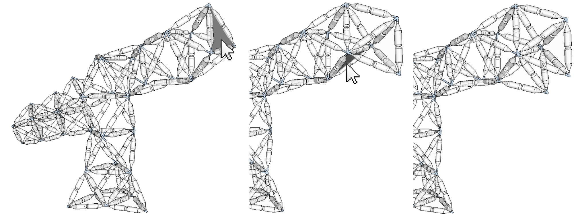
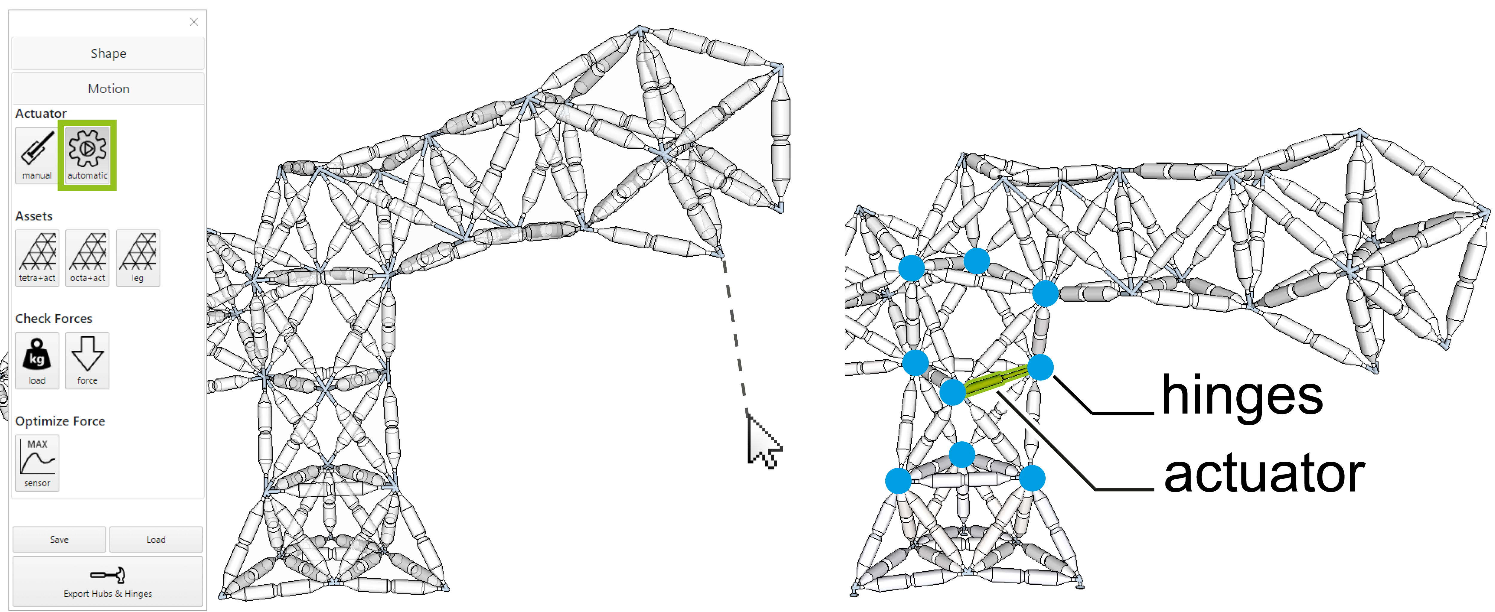
step 2: Adding movement. TrussFormer provides three different approaches to animate the structures, ranging from (1) automated placement (for novice users), through (2) placing elements with predefined motion, called assets, to (3) manual placement (as users acquire engineering knowledge). To add movement using the demonstrate movement tool, users pull the T-Rex head downwards. TrussFormer responds by placing an actuator that turns the T-Rex body into a structure that can bend down, as shown in the figure below.
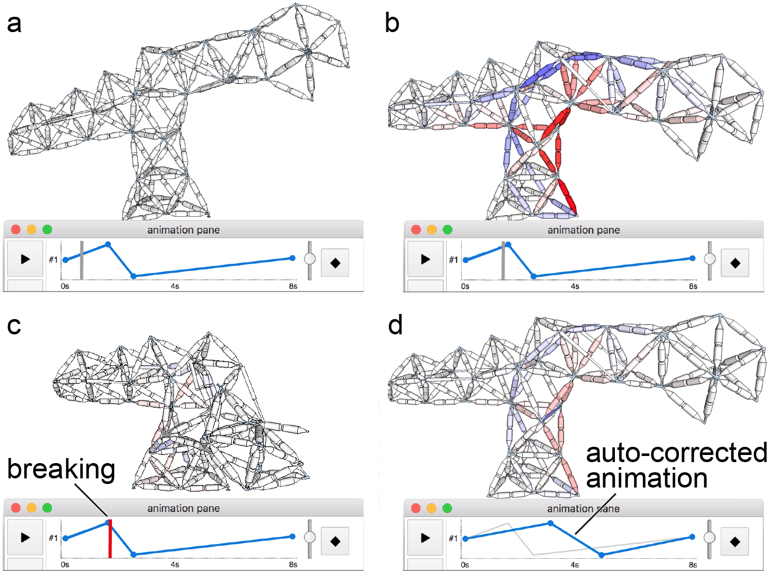
step 3: Stability check across poses. During this step, TrussFormer verifies that the mechanism is structurally sound. In the background, TrussFormer finds the safe range of expansion and contraction of the placed actuator by simulating the occurring forces in a range of positions. If there is a pose where the forces exceed the pre-determined breaking limits or the structure would tip over, TrussFormer sets the limits for the actuator so it will not extend beyond them. This check prevents users from producing invalid configurations.
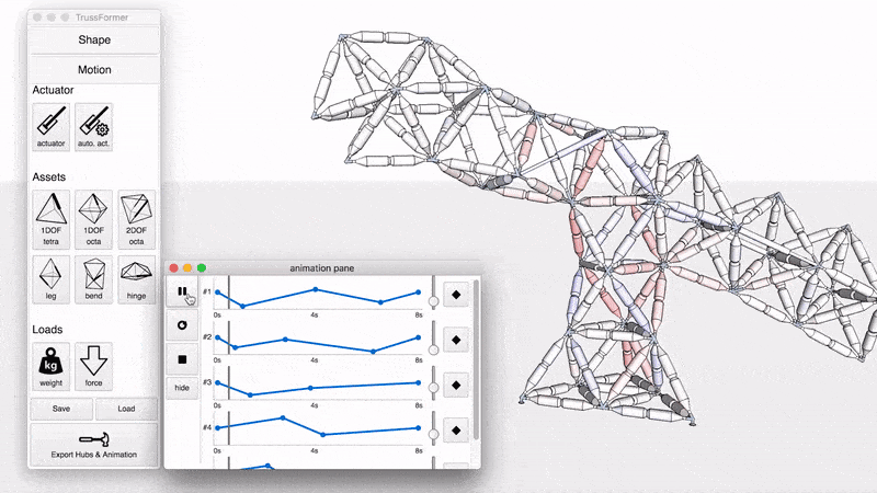
step 4: Animation. To animate the structure users open the animation pane in the toolbar, as shown in the figure below. First, they control the movement of the structure manually using sliders, to try out the movement. When they find the desired pose, they simply add it as a keyframe to the animation timeline. With this TrussFormer allows users to orchestrate the movement of all actuators using a simple timeline/keyframe editor. Here, user programs a “feeding” behaviour, where the T-Rex opens its mouth while reaching down and waving its tail.
step 5: Checking the forces during the motion. Once the animation has been defined, TrussFormer computes the dynamic forces. In the figure below, (a) the user creates an animation that moves the T-Rex body up and down. (b) TrussFormer computes the forces while T-Rex’s body comes back up quickly after dipping down; the large acceleration of the long neck leads to very high inertial forces, exceeding the breaking limit of the construction, (c) causing the structure to fail at the indicated time point. These situations are hard to foresee, because the inertial forces can be multiple times higher than the static load in the structure. (d) TrussFormer addresses this by automatically correcting the animation sequence by either limiting the acceleration or the range of the movement, assuring that the structure will now withstand the movement.
step 6: Fabrication. When users are satisfied with their design (structure, movement and animation), they click the fabricate button. This invokes (1) TrussFormer’s hinge generation algorithm, which analyzes the structure’s motion and generates the appropriate 3D printable hinge and hub geometries, annotated with imprinted IDs for assembly. In the case of the T-Rex, the system exports 42 3D printed hubs, consisting of 135 unique hinging pieces.
(2) Next, TrussFormer exports the created animation patterns as Arduino code that users upload to their microcontroller. (3) Lastly, it outputs a specification file, containing the force, speed, and motion range of the actuators, in order to achieve the desired animation pattern. Users find these actuators as standardized components.
Conclusion
Our main contribution is this end-to-end system that enables non-expert users to create large-scale kinetic structures, such as the devices used in large-scale animatronics.
TrussFormer helps users in the 3 main steps along the design process. (1) It enables users to animate large truss structures by adding linear actuators to them. It offers three tools for this purpose: manual actuator placement, placement of assets performing predefined motion, and creating motion by demonstration. (2) TrussFormer validates the design in real time against static forces, static forces across all poses, and dynamic forces. (3) TrussFormer automatically generates the necessary 3D printable hinges for fabricating the structure. Its algorithm determines the placement and configuration of the hinges and their exact dimensions.
Talk at UIST2018
more:
official project page
Robert Kovacs, Anna Seufert, Ludwig Wall, Hsiang-Ting Chen, Florian Meinel, Willi Müller, Si-jing You, Maximilian Brehm, Jonathan Striebel, Yannis Kommana, Alexander Popiak, Thomas Bläsius, and Patrick Baudisch
In Proceedings of the SIGCHI Conference on Human Factors in Computing Systems (CHI ’17)
full paper: PDF
ACM Digital Library
3D models on thingiverse
TrussFab on Instructables
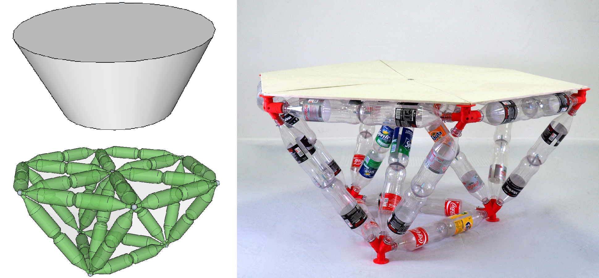
TrussFab is an integrated end-to-end system that allows users to fabricate large scale structures that are sturdy enough to carry human weight. TrussFab achieves the large scale by complementing 3D print with plastic bottles.
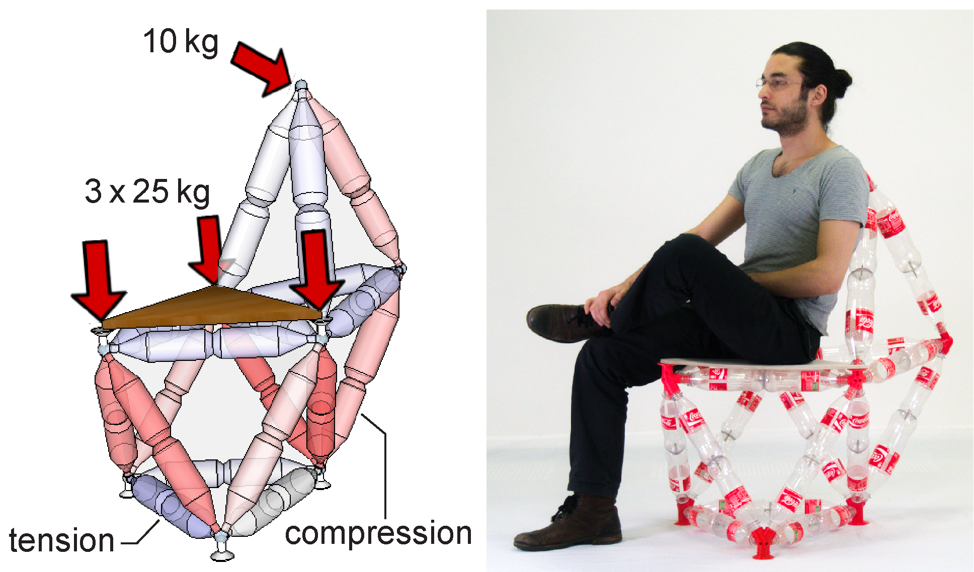
Unlike previous systems that stacked bottles as if they were “bricks”, TrussFab considers them as beams and uses them to form structurally sound node link structures based on closed triangles, also known as trusses. TrussFab embodies the required engineering knowledge, allowing non-engineers to design such structures.
While freestanding bottles tend to break easily, truss structures essentially consist of triangles. In such an arrangement, it is the structure that prevents de-formation, not the individual bottle. The main strength of trusses is that they turn lateral forces (aka bending moments) into tension and compression forces along the length of the edges (aka members). Bottles make great members: while they buckle easily when pushed from the side, they are very strong when pushed or pulled along their main axis. TrussFab affords building trusses by combining tetrahedra and octahedra into so-called tetrahedral honeycomb structures.
Walkthrough of the TrussFab system
step 1: Automatic conversion. One way to create TrussFab structures is to convert an existing 3D model using Truss-Fab’s converter. As shown in the figure below, this converts the volume of the model into a tetrahedral honeycomb structure, allowing it to bear substantial load.
step 2: Editing. We implemented TrussFab’s editor as an extension to the 3D modeling software SketchUp. TrussFab’s editor offers all the functionalities of the original SketchUp system, plus custom functions that help users create sturdy structures. In particular, TrussFab’s editor offers primitives that are elementary trusses (tetrahedra and octahedra), tools that create large beams in the form of trusses, and tools for tweaking the shape of structures, while maintaining their truss structure. TrussFab’s integrated structural analysis calculates the internal forces in the structure and warns users if it would brake.
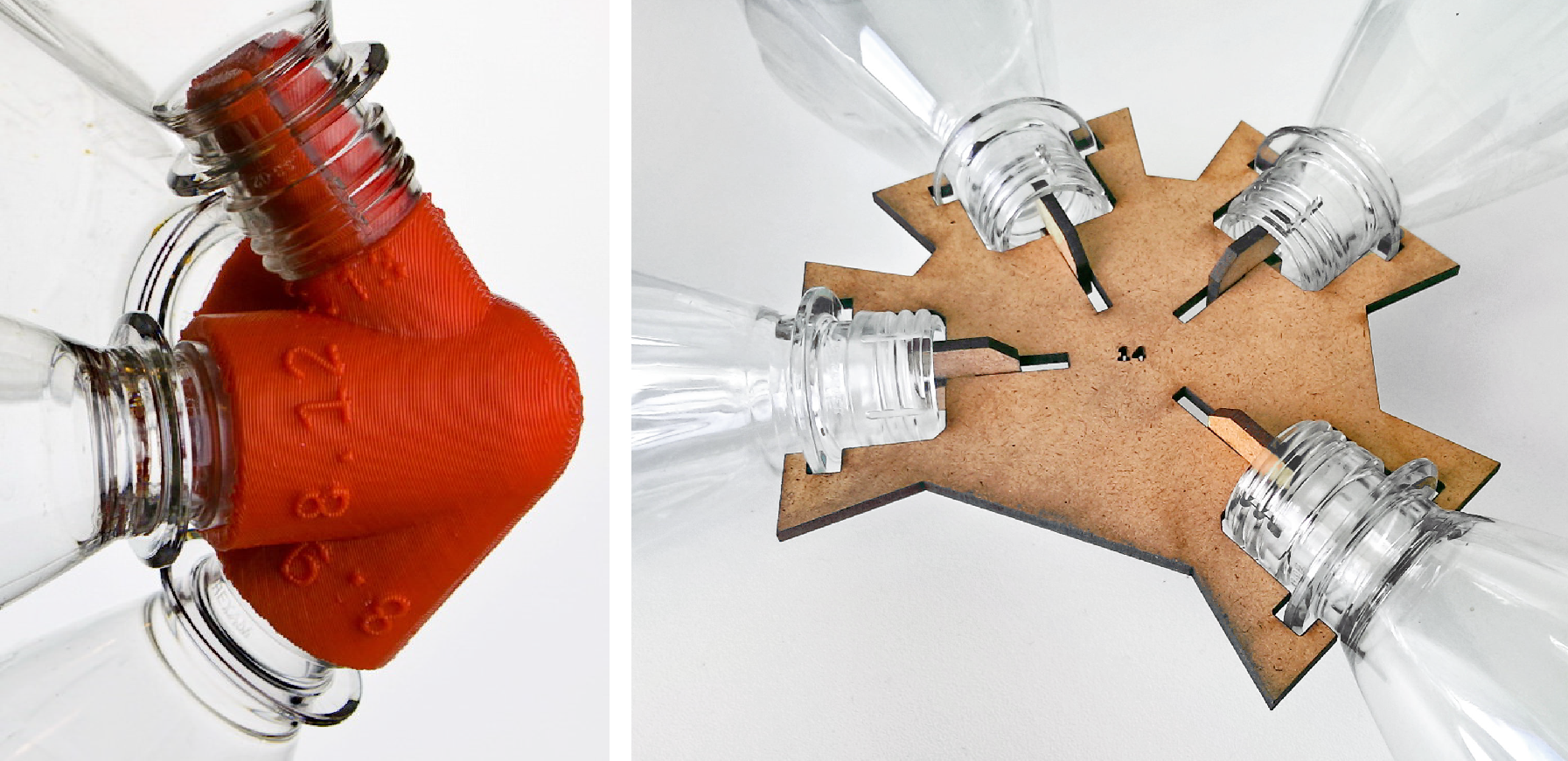
step 3: Hub generation. After designing a structure, TrussFab’s hub generator generates the 3D models of all hubs. The system genarates 3D printable hubs for spacial structures and laser-cuttable 2D hubs for facades, as shown in the figure below.
step 4: Fabrication. Users then send the 3D model files produced by the hub generator to one or more 3D printers in order to manufacture them.
step 5: Assembly. Users finally manually assemble their structures by following the unique IDs embossed into each hub.
We have validated our system by designing and fabricating tables and chairs, a 2.5 m bridge strong enough to carry a human, and a 5 m high pavilion consisting of 1280 bottles and 191 3D printed hubs, presented at CHI'17 in Denver.
Daily Planet documented the building process of the pavilion at CHI2017
Conclusion
TrussFab is an integrated end-to-end system that allows users to fabricate large structures that are sturdy enough to carry human weight on desktop 3D printers. Unlike previ-ous systems that built on up-cycled plastic bottles com-bined with 3D print, TrussFab considers bottles not as “bricks”, but as beams that form structurally sound node link structures also known as trusses, allowing users to handle the forces resulting from scale and load. TrussFab embodies the required engineering knowledge, allowing non-engineers to design such structures and allows users to validate their designs using integrated structural analysis.
official project page
media article on ArchDaily
If you are interested in trying out our beta software, drop me an email: robertkovax@yahoo.com
Harshit Agrawal, Udayan Umapathi, Robert Kovacs, Johannes Frohnhofen, Hsiang-Ting Chen, Stefanie Mueller, Patrick Baudisch
In Proceedings of the 28th Annual ACM Symposium on User Interface Software & Technology (UIST ’15).
full paper: ACM digital library, PDF
make it on instructables
Protopiper is a computer aided, hand-held fabrication device that allows users to sketch room-sized objects at actual scale. The key idea behind protopiper is that it forms adhesive tape into tubes as its main building material, rather than extruded plastic or photopolymer lines. Since the resulting tubes are hollow they offer excellent strength-to-weight ratio, thus scale well to large structures.
The device itself is an assembly line: the tape is drawn from the roll, shaped into a tube, sealed together, and finally cut off.
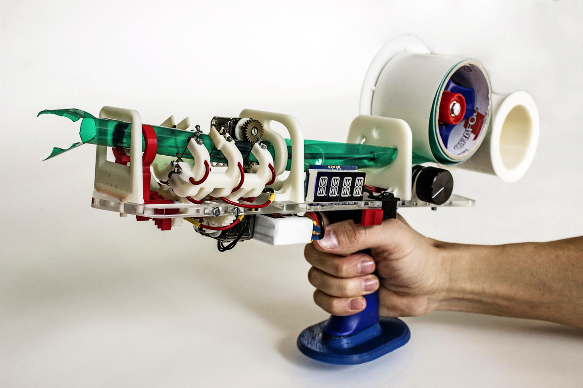
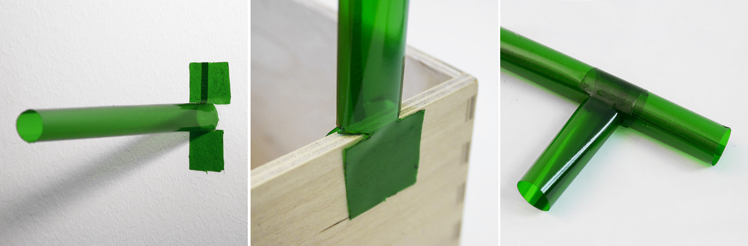
Protopiper provide the tubes with highly versatile wing connectors—one at each end. Wing connectors connect tubes to flat or curved surfaces, such as walls or ceilings, or other tubes.
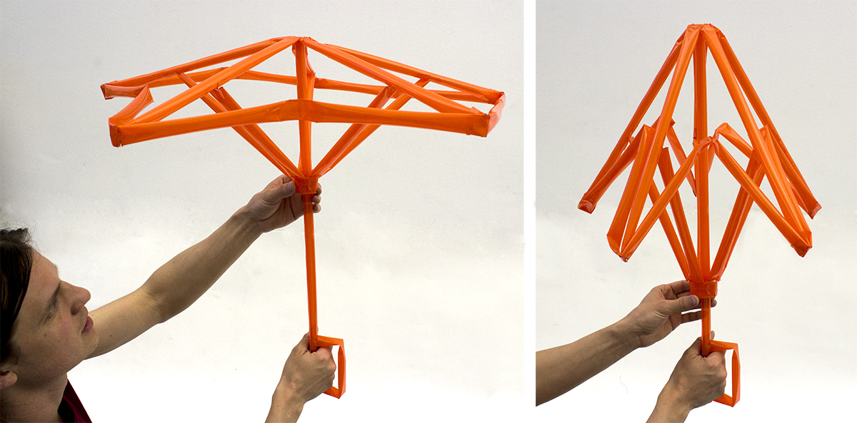
Protopiper’s tubes also afford creating simple mechanisms. By creasing them, for example, users form hinges. Hinges allow for moving mechanisms, like the opening-closing umbrella.
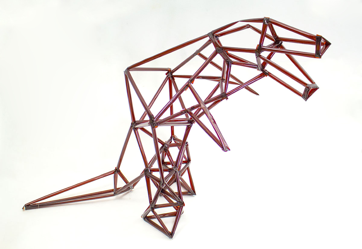
Protopiper works equally well for freeform expression, such as the T-Rex sculpture.
presentation at UIST 2015
more
GIZMODO article
official project page
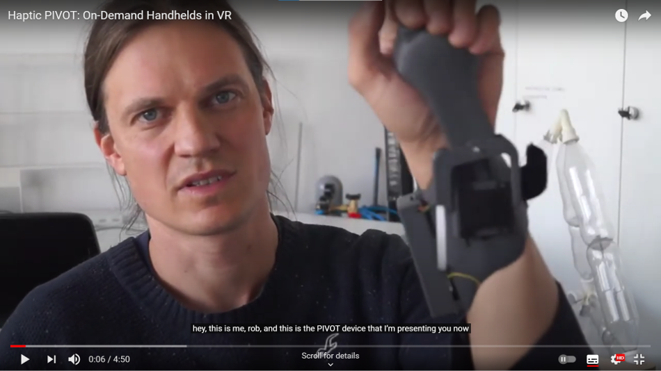
Haptic PIVOT: On-Demand Handhelds
in VR
Robert Kovacs, Eyal Ofek, Mar Gonzalez Franco, Alexa Fay Siu, Sebastian Marwecki, Christian Holz, and Mike Sinclair
In Proceedings of the 33th Annual ACM Symposium on User Interface Software and Technology (UIST ’20)
paper: PDF
ACM Digital Library
ABSTRACT
Hapric PIVOT is a wrist-worn haptic device that renders virtual objects into the user’s hand on demand. Its simple design comprises a single actuated joint that pivots a haptic handle into and out of the user’s hand, rendering the haptic sensations of grasping, catching, or throwing an object – anywhere in space.
Unlike existing hand-held haptic devices and haptic gloves, PIVOT leaves the user’s palm free when not in use, allowing users to make unencumbered use of their hand. PIVOT also enables rendering forces acting on the held virtual objects, such as gravity, inertia, or air-drag, by actively driving its motor while the user is firmly holding the handle. When wearing a PIVOT device on both hands, they can add haptic feedback to bimanual interaction, such as lifting larger objects. In our user study, participants (n=12) evaluated the realism of grabbing and releasing objects of different shape and size with mean score 5.19 on a scale from 1 to 7, rated the ability to catch and throw balls in different directions with different velocities (mean=5.5), and verified the ability to render the comparative weight of held objects with 87% accuracy for ~100g increments.
![]()
Robert Kovacs, Eyal Ofek, Mar Gonzalez Franco, Alexa Fay Siu, Sebastian Marwecki, Christian Holz, and Mike Sinclair
In Proceedings of the 33th Annual ACM Symposium on User Interface Software and Technology (UIST ’20)
paper: PDF
ACM Digital Library
ABSTRACT
Hapric PIVOT is a wrist-worn haptic device that renders virtual objects into the user’s hand on demand. Its simple design comprises a single actuated joint that pivots a haptic handle into and out of the user’s hand, rendering the haptic sensations of grasping, catching, or throwing an object – anywhere in space.
Unlike existing hand-held haptic devices and haptic gloves, PIVOT leaves the user’s palm free when not in use, allowing users to make unencumbered use of their hand. PIVOT also enables rendering forces acting on the held virtual objects, such as gravity, inertia, or air-drag, by actively driving its motor while the user is firmly holding the handle. When wearing a PIVOT device on both hands, they can add haptic feedback to bimanual interaction, such as lifting larger objects. In our user study, participants (n=12) evaluated the realism of grabbing and releasing objects of different shape and size with mean score 5.19 on a scale from 1 to 7, rated the ability to catch and throw balls in different directions with different velocities (mean=5.5), and verified the ability to render the comparative weight of held objects with 87% accuracy for ~100g increments.
Presentation at UIST’20
PIVOT’s key benefits:
-
catching and throwing flying objects
-
grasping and releasing stationary objects
-
simulates dynamic forces provided by the grabbed object
such as weight, inertia, or drag
-
leaves the users palm completely free for real-world perations
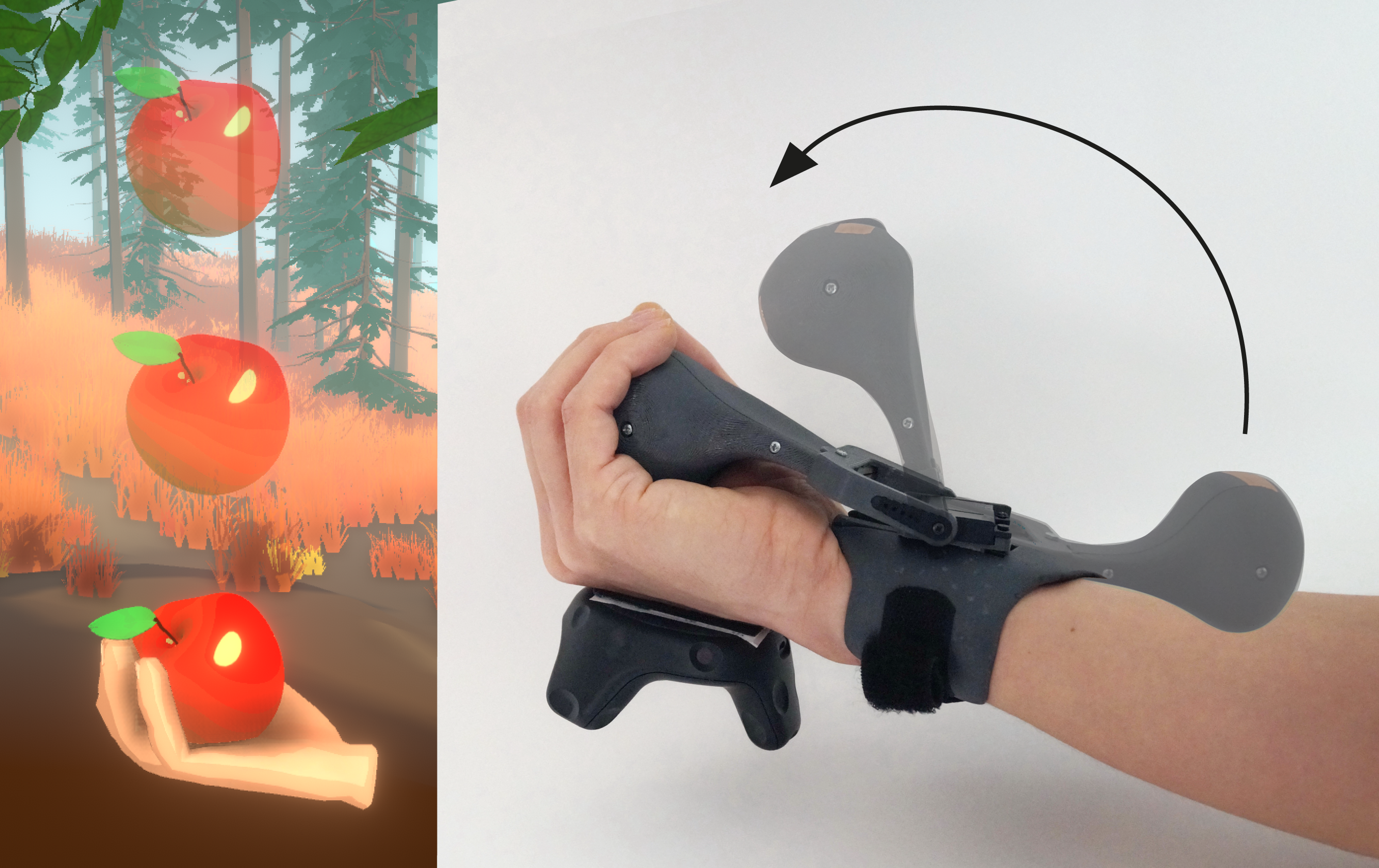
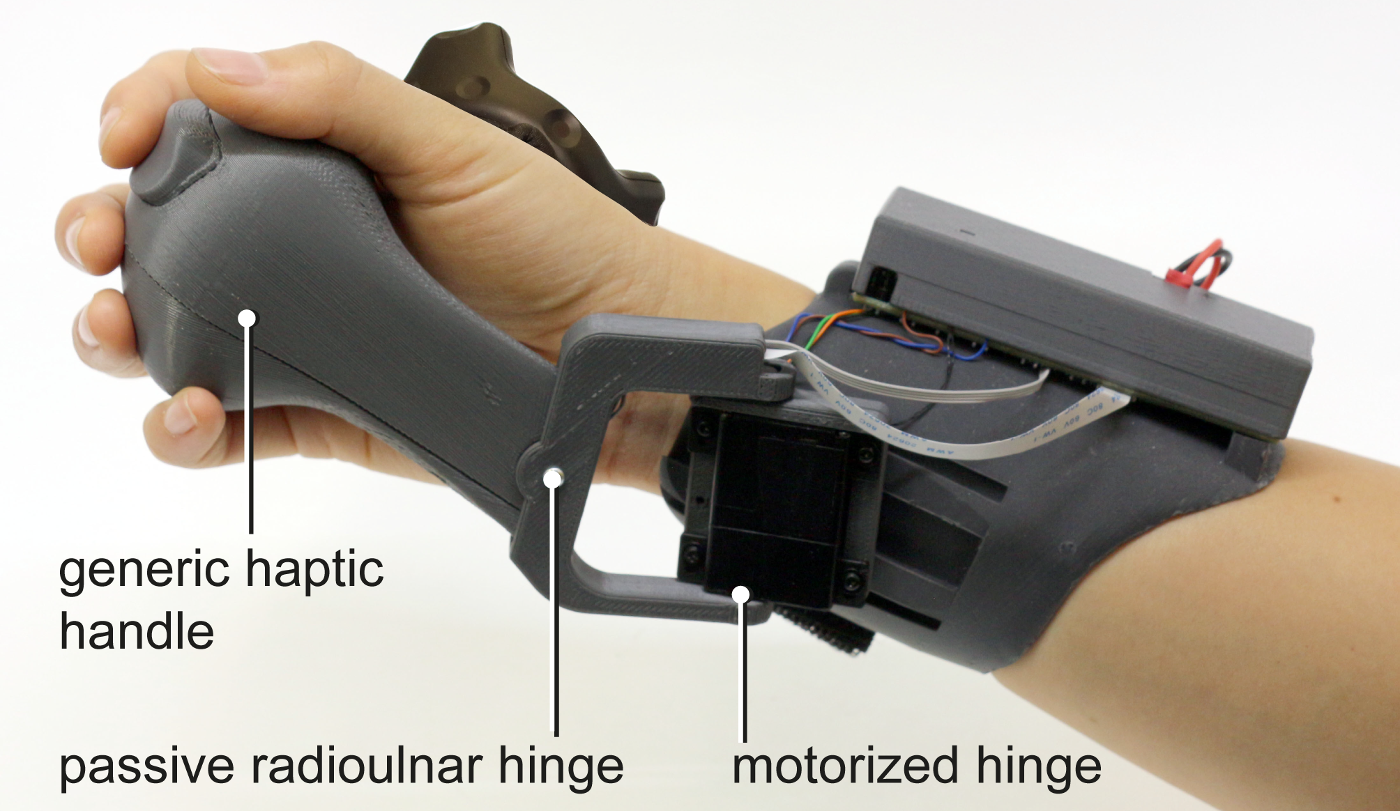
PIVOT’s handle acts as a generic proxy while additionally offering similar ergonomics and functionality as conventional VR controllers, including touch sensing, a trigger button, and vibrotactile feedback. The device design includes a back-drivable motorized hinge for the flexing wrist movement and an additional passive radioulnar hinge that enables the hand to move sideways (here: up-down) while holding the handle.
Touching and grasping virtual objects
PIVOT’s main capability is rendering haptic sensations for acquiring, grasping and releasing virtual objects. When the user reaches for an object, PIVOT moves its handle towards the user’s hand proportionally with the distance to the virtual object. As a result, PIVOT’s handle touches the user’s hand in synchrony with the virtual object.Catching and throwing
Using its quick actuation mechanisms, PIVOT can naturally render haptic feedback in response to throwing and catching virtual objects. The main difference to grasping stationary objects is in PIVOT’s process loop that predicts the contact with the flying object. When a potential object is flying towards the hand, PIVOT starts moving the handle in advance, accounting for the latency of the system and placing it in the user’s hand at the time the user expects the object to make contact.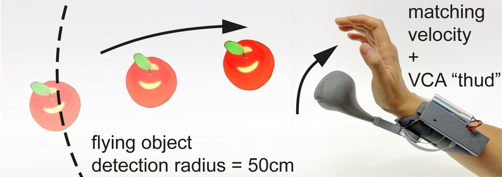
Force rendering
In addition to touch feedback, PIVOT can produce a sensation of dynamic forces acting on the handheld virtual object, like gravity, springiness, inertia or drag. It does this by continuously actuating its handle motor, while it is firmly grasped by the user.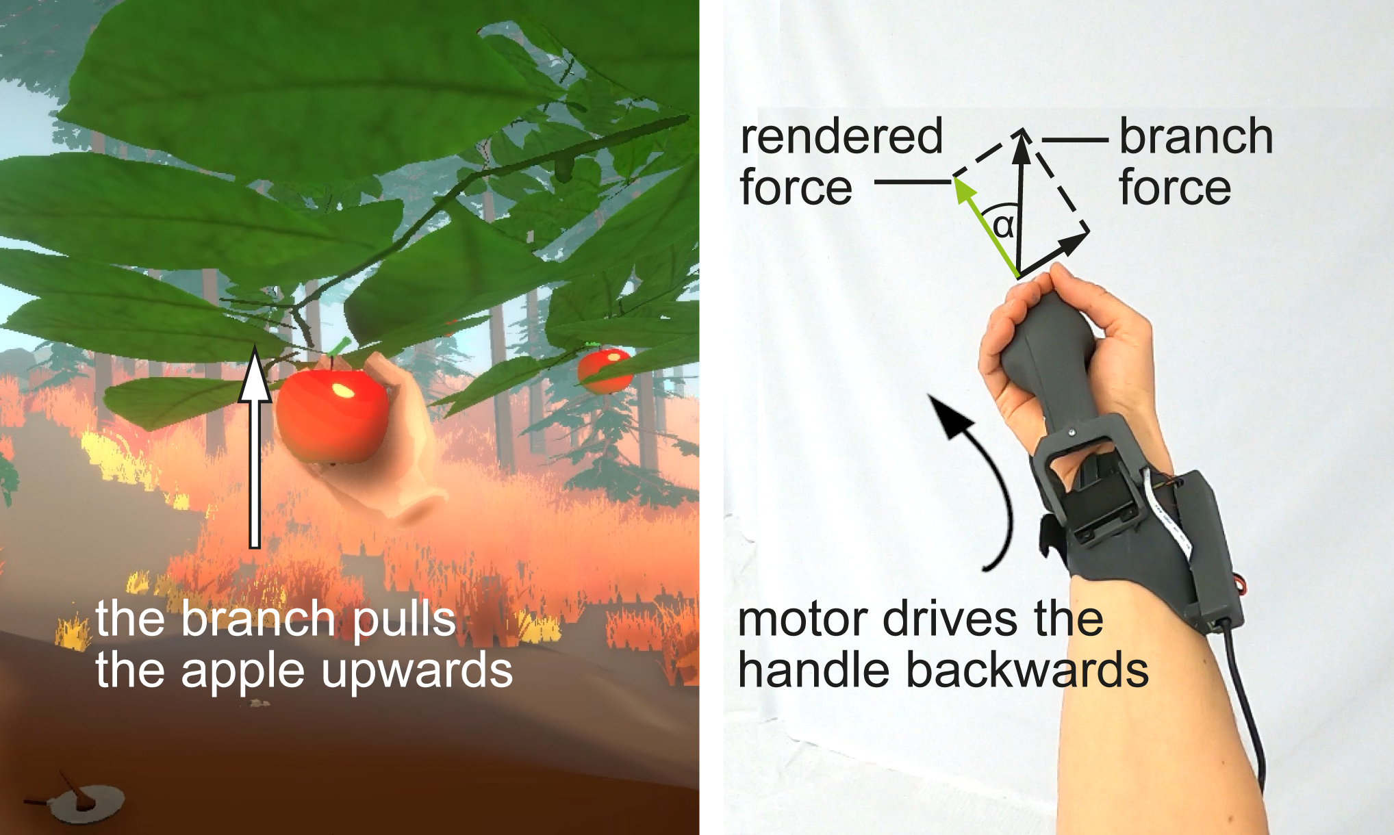
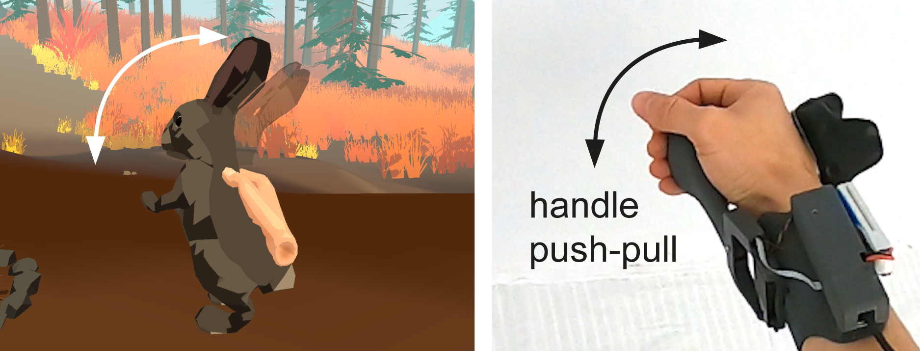
An example for rendering force feedback for dynamic animated objects, such as a wiggling bunny. User perceives the inertia of the wiggling bunny through quickly actuating PIVOT’s handle back and forth.
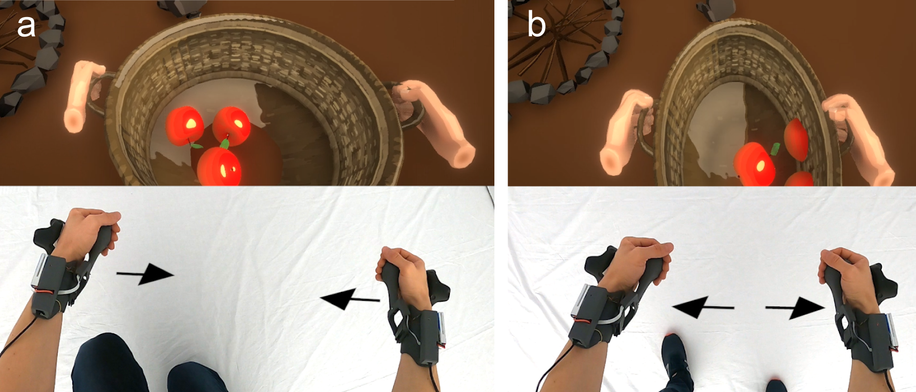
PIVOT also supports two-handed operation to render haptic feedback in response to larger and heavier virtual objects. Because the device cannot physically constrain the two hands to each other, it renders large objects as compliant and applies coupled force feedback on both hands.
Free-hand use and summoning on-demand
One of PIVOT’s key benefits is that it lets users use their hands freely. As shown in Figure 8a, the folded idle state affords free‑hand interaction, such as resting the hand on the table, operating tangible objects, such as a keyboard and mouse, or placing up the headphones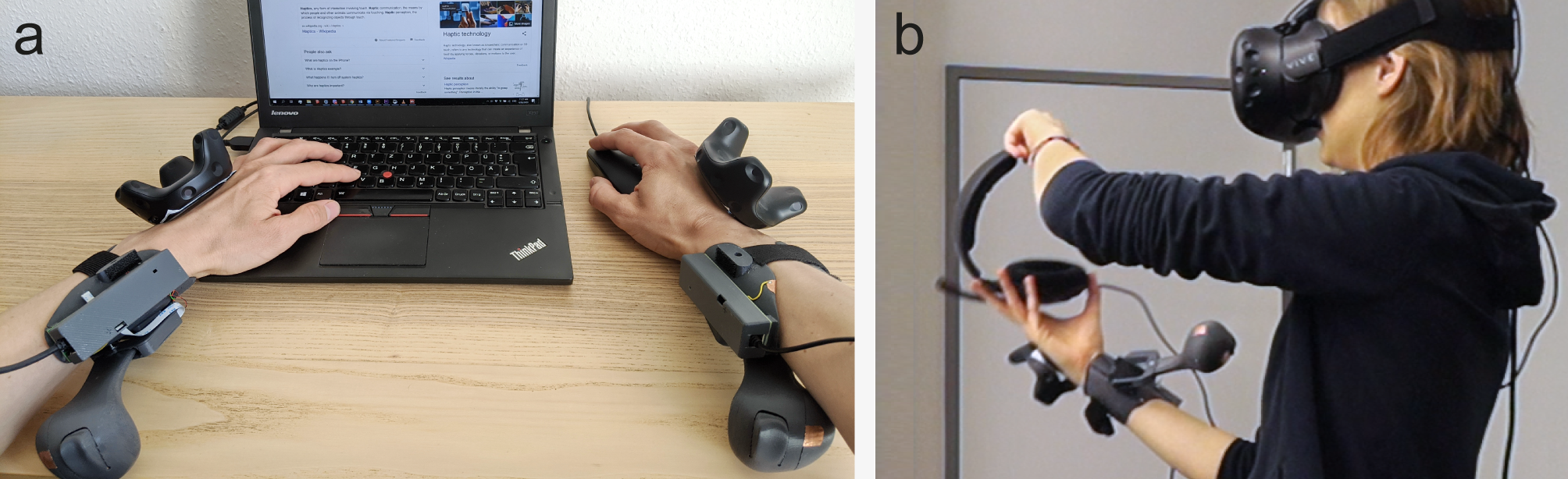
Hardware
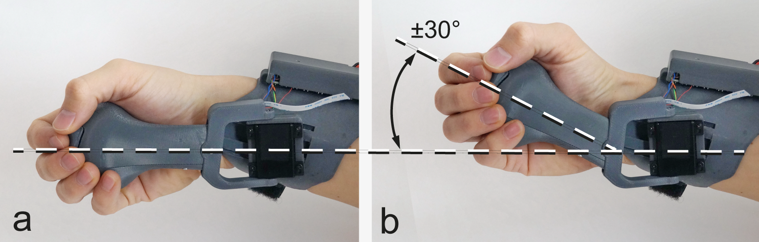
The servo actively pivots the handle around the slanted vertical axis, while the handle affords passive radioulnar motion to accommodate natural hand tilting. A sliding rail mount on the hand-cuff enables adjustment to individual hand sizes.
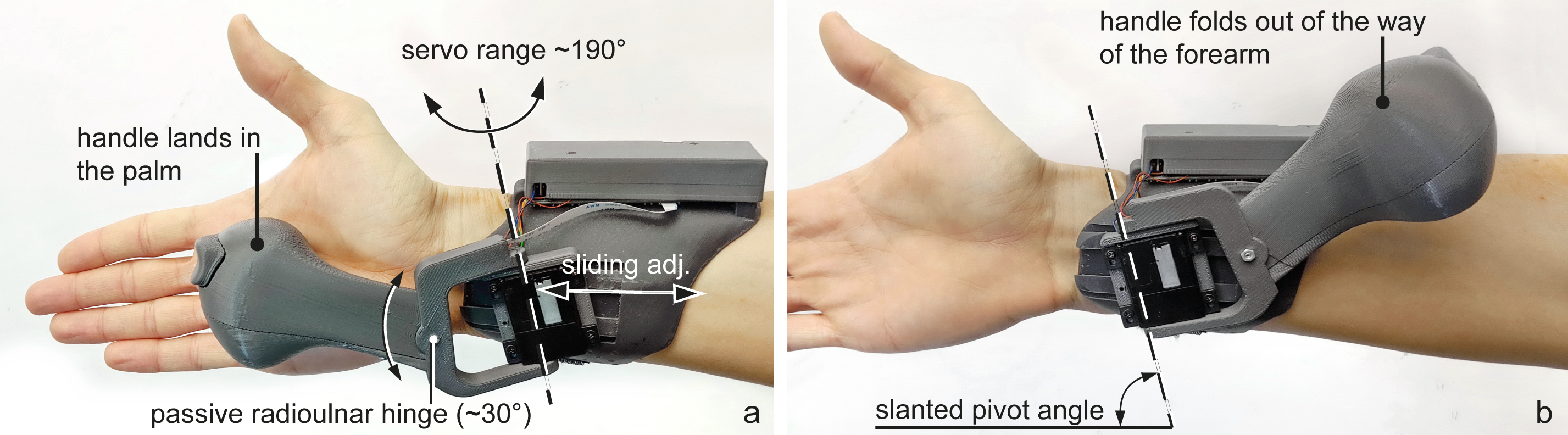
The passive, friction based radioulnar hinge enables the hand to move when holding the handle (here: up-down).
The device is equipped with a 32 bit, 180 MHz Teensy 3.6 microcontroller that controls the servo motor, gathers the sensory information and communicates with the PC.
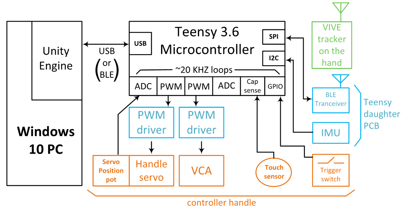
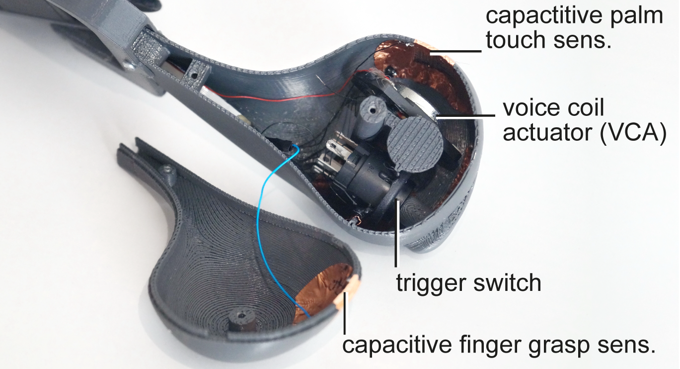
The inside of the handle containing the trigger, capacitive sensing, and the VCA. We use the Teensy’s built-in active loading capacitive sensing functionality to detect touch on the copper-based patches placed on the inside of the handle at four distinct locations. The handle also contains a VCA to render vibrotactile feedback as well as a trigger button as commonly found in VR controllers.
User study
We conducted a user study to evaluate PIVOT’s ability to simulate: (1) grasping sensation for a variety of objects, (2) catching & throwing of objects at different speeds and directions, and (3) perceptual illusion of weight of an object. We recruited twelve participants (ages 19-26, mean=22). Each participant performed a series of tasks inside VR using PIVOT. After each task, participants also completed an offline questionnaire.
Task 1: Grasping objects of various shape and size
In the first task, we measured PIVOT’s ability to render a grasping sensation. We asked participants to reach towards, grab, move and release virtual objects of different size (Figure 15, 1-4) and shape (5-9). Note the size range includes the diameter of the handle of the wrench and the handle of the cup, but not the full object.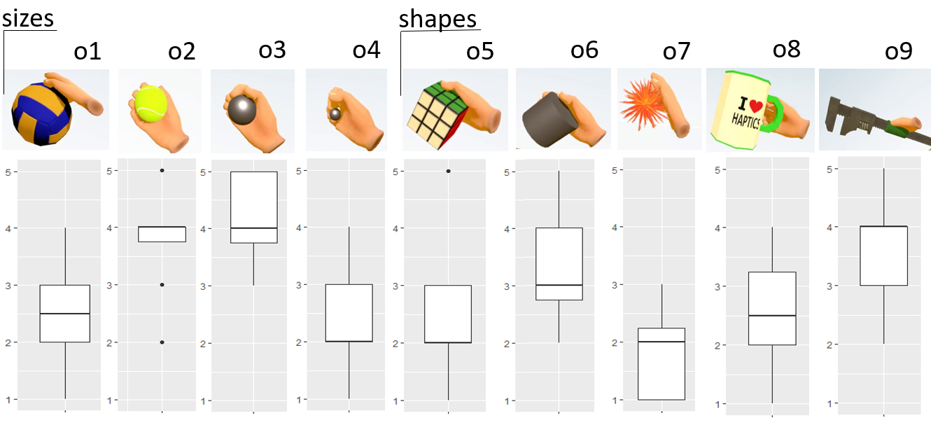
Participants rated their experience in response to the question “How realistic does the grab & hold haptic experience feel?” on a 1 (not real at all) to 5 (very realistic) Likert scale directly inside the HMD.
Participants found it realistic (average score 3.9) to hold spheres of 5 cm (the most similar shape to PIVOT’s handle, o3) and within a tolerance of ±2cm in diameter (o2). Objects beyond this range (o1 and o4) were not perceived as realistic (V = 66, p < 0.01). This indicates that users accept slight discrepancies between the visual and actual size of objects.
Task 2: Catching and throwing virtual objects
In the second task, we measured PIVOT’s ability to enable catching and throwing. In addition, were aiming to identify potential ergonomic differences while catching and throwing a ball coming from different directions. Even though PIVOT moves together with the user’s hand in space, there are certain anatomic differences in catching and throwing when the palm is facing upwards, downwards, to the front or to the side. We tasked participants to catch a virtual ball thrown at them from two meters away coming from four different directions (front, side, down, up).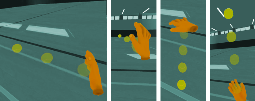
Catching: Participants found the haptic experience for catching realistic (Figure 17), with an average score of 3.5 ±1 (mean, sd). No significant differences were found for the direction of the ball, despite the balls coming from the front were found a bit the less realistic (avg score = 3.3), most likely because of the ergonomics of the device. Participants found catching faster balls more realistic (Pearson correlation of r=0.25, p < 0.01). We did not simulate gravity, which, with the slow balls, might have been more apparent.
Throwing: Participants found the haptic experience of throwing more realistic than that of catching (Wilcoxon signed rank paired test p < 0.001), with an average score of 4 ±1 (mean, sd). The reason for this might be the previously described importance of self-generated actions for haptic acceptance [5]. No significant differences were found in the realism between throwing to the side, up and to the front. Only for the down direction we found a significant negative correlation (r=-0.31, p < .05). Further investigation would be necessary to understand this effect. For the three other directions, the correlation of speed and realism was maintained: the fastest the throw the more realistic it seemed (Pearson correlation r=0.24, p < 0.01).
Task 3: Perception of weight
In the last task, we measured PIVOT’s ability to produce the perception of weight. We asked participants to grab three different virtual balls and select the one they perceived to be heaviest and the one they found the lightest (Figure 18). Participants naturally assessed the balls weight by holding the balls upwards, downwards, turning them, and weighting with up-down movements. The rendered weights of the objects were 90g, 200g and 300g (the force exerted at the end of the handle lever). Similarly as illustrated in Figure 5, the device was rendering only the perpendicular component of the gravitational force to the plane of the palm. This resulted in full weight sensation when the palm was facing upwards or downwards, and proportionally less in the in-between positions.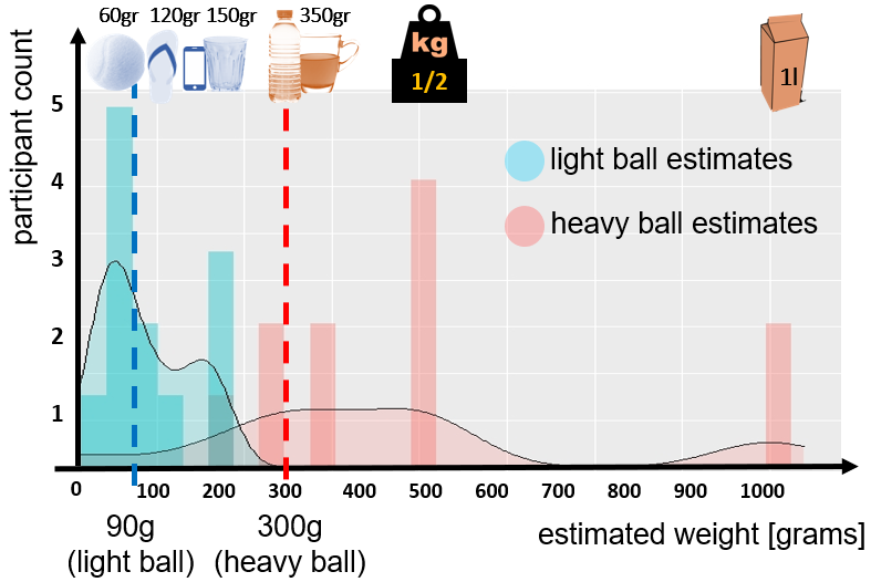
Overall, there was a slight tendency to overestimate the weight. This could be a normal human tendency or a fatigue effect. Two participants were clear outliers in overestimating.
Conclusion
In this paper, we presented a novel interactive haptic device for use in AR and VR scenarios. Unlike existing commercial controllers and haptic devices presented in recent research projects, PIVOT presents an approach that dynamically appears and vanishes a haptic proxy in the user’s palm. This enables compelling haptic effects and force rendering, as well as free-hand interactions with physical objects in the real world. What enables PIVOT’s unique capability is a forearm-grounded pivoting mechanism that rotates a handle into and out of the user’s palm on demand. We demonstrated several use-cases of this key feature in this paper, such as grasping, catching, and throwing virtual objects, which PIVOT renders in an analog manner. In addition, our controller enables rendering dynamic forces excreted by the grasped objects. In our user study, participants rated the use of PIVOT as a realistic proxy and highlighted the ergonomics of the design that made them feel like their hand was in direct contact with the object. These results support PIVOT’s potential for future use.
more at:
Microsoft Research blog post
FormFab: Towards Shape Exploration in Interactive Fabrication
Stefanie Mueller, Anna Seufert, Huaishu Peng, Robert Kovacs, Kevin Reuss, François Guimbretière, Patrick Baudisch
In Proc. TEI'19. Full Paper
paper: PDF
ACM Digital Library
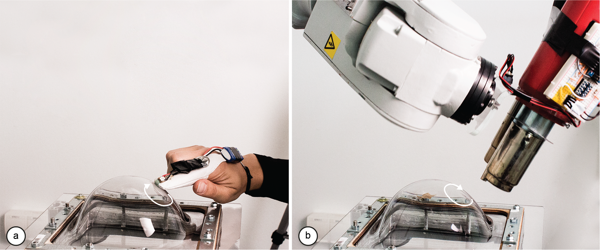
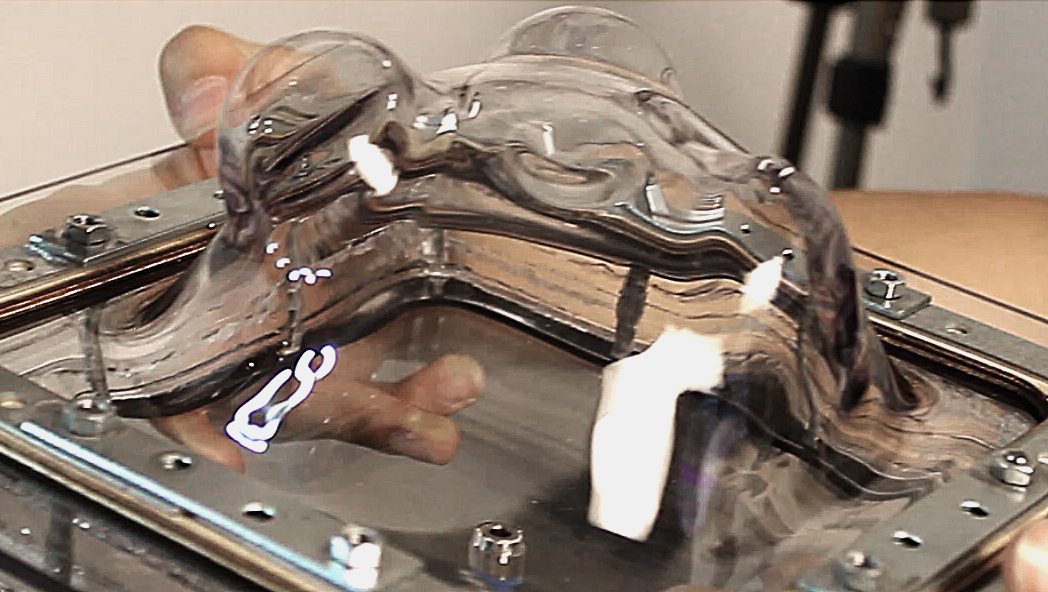
FormFab is an interactive fabrication system that can change a workpiece’s shape continuously while the user is interacting. This enables users to explore different sizes of a shape with a single interaction rather than in multiple turns. We accomplish this using a process called formative fabrication, which rather than adding or subtracting, reshapes the existing material. In our system, users interactively control a pneumatic air pump that applies either pressure or vacuum to a compliant thermoplastic sheet, thereby pushing the material outwards or pulling it inwards.
![]()
To achieve this, FormFab does not add or subtract material but instead reshapes it (formativefabrication). A heat gun attached to a robotic arm warms up a thermoplastic sheet until it becomes compliant; users then control a pneumatic system that applies either pressure or vacuum thereby pushing the material outwards or pulling it inwards.
![]()
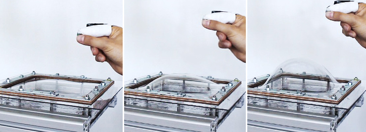
First, users draw an outline of the area they want to reshape using their index finger. When the user removes the finger, the path is beautified by our software. The robotic arm then warms up the areausing a heat gun.
After the material has reached its compliance point, the robotic arm moves out of the way. The user can then perform a pinch gesture, which activates the pneumatic system. If the user’s hand moves away from the workpiece, the pneumatic system increases the air pressure and the compliant area inflates.
![]()
To track the user interaction, FormFab users wear a motion capture marker and a pressure sensor on their index finger. The marker is detected by a motion capture system (OptiTrack) and used to determine wherethe user is interacting on the workpiece. In addition, the pressure sensor is used to determine the beginning and end of the interaction.
![]()
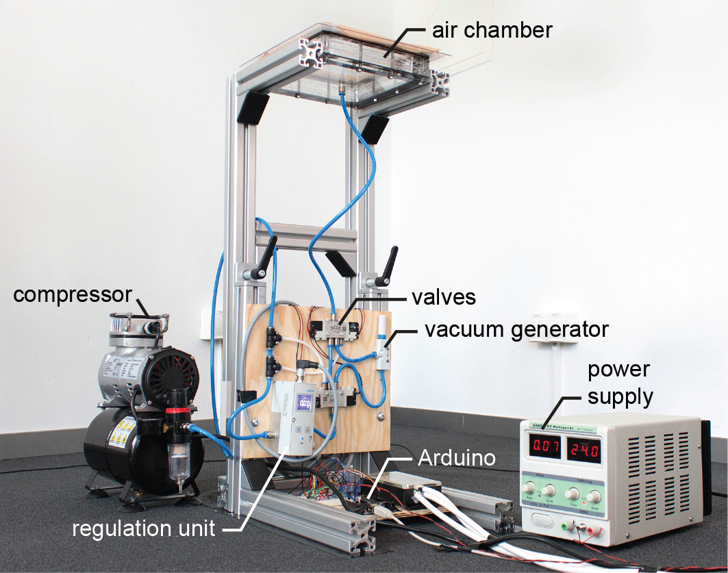
To reshape the workpiece, FormFab uses a compressed air. The air is guided through different valves, depending on whether pressure or vacuum should be applied
to the workpiece.
![]()
More Information:
https://hpi.de//baudisch/projects/formfab.html
https://hcie.csail.mit.edu/research/formfab/formfab.html
Stefanie Mueller, Anna Seufert, Huaishu Peng, Robert Kovacs, Kevin Reuss, François Guimbretière, Patrick Baudisch
In Proc. TEI'19. Full Paper
paper: PDF
ACM Digital Library
FormFab is an interactive fabrication system that can change a workpiece’s shape continuously while the user is interacting. This enables users to explore different sizes of a shape with a single interaction rather than in multiple turns. We accomplish this using a process called formative fabrication, which rather than adding or subtracting, reshapes the existing material. In our system, users interactively control a pneumatic air pump that applies either pressure or vacuum to a compliant thermoplastic sheet, thereby pushing the material outwards or pulling it inwards.
To achieve this, FormFab does not add or subtract material but instead reshapes it (formativefabrication). A heat gun attached to a robotic arm warms up a thermoplastic sheet until it becomes compliant; users then control a pneumatic system that applies either pressure or vacuum thereby pushing the material outwards or pulling it inwards.
First, users draw an outline of the area they want to reshape using their index finger. When the user removes the finger, the path is beautified by our software. The robotic arm then warms up the areausing a heat gun.
After the material has reached its compliance point, the robotic arm moves out of the way. The user can then perform a pinch gesture, which activates the pneumatic system. If the user’s hand moves away from the workpiece, the pneumatic system increases the air pressure and the compliant area inflates.
To track the user interaction, FormFab users wear a motion capture marker and a pressure sensor on their index finger. The marker is detected by a motion capture system (OptiTrack) and used to determine wherethe user is interacting on the workpiece. In addition, the pressure sensor is used to determine the beginning and end of the interaction.
To reshape the workpiece, FormFab uses a compressed air. The air is guided through different valves, depending on whether pressure or vacuum should be applied
to the workpiece.
Conclusion
In this paper, we showed a first prototype implementation of an interactive fabrication system that provides the user with physical feedback while the user is interacting. While the first step of selecting the area still followed the turntaking model, the second step of defining the size of the shape provided the user with simultaneous physical feedback, thereby bringing the principles of direct manipulation to the editing of physical objects.More Information:
https://hpi.de//baudisch/projects/formfab.html
https://hcie.csail.mit.edu/research/formfab/formfab.html
Oliver Schneider, Jotaro Shigeyama, Robert Kovacs, Thijs Jan Roumen, Sebastian Marwecki, Nico Boeckhoff, Daniel Amadeus Gloeckner, Jonas Bounama, Patrick Baudisch
In Proceedings of the 31th Annual ACM Symposium on User Interface Software and Technology (UIST ’18)
paper: PDF
ACM Digital Library
DualPanto is a haptic device that enables blind users to track moving objects while acting in a virtual world.
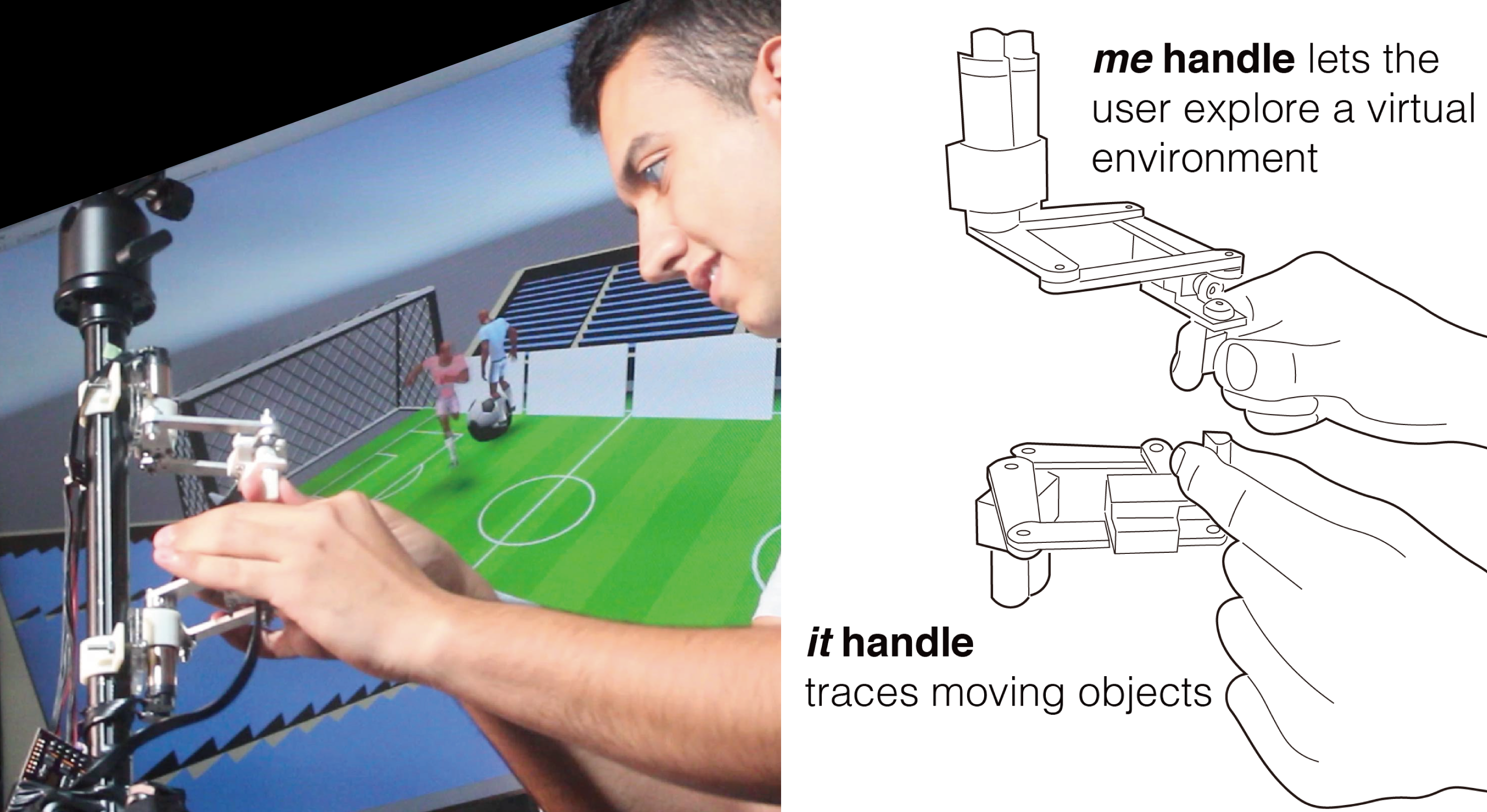
As shown in the figure abowe (b), the device features two handles. Users interact with DualPanto by actively moving the me handle with one hand and passively holding on to the it handle with the other. DualPanto applications generally use the me handle to represent the user’s avatar in the virtual world and the it handle to represent some other moving entity, such as the opponent in a soccer game.
interacting with DualPanto

me handle: As shown in the figure above, DualPanto’s applications generally use the me handle to represent the user’s avatar in the virtual world.
(a) The user moves around and explores the virtual environment, such as a series of rooms in a shooter game, by moving the me handle. The device uses a direct 1:1 mapping, similar to the mapping of a touch screen; returning the handle to the same location in the physical world returns the avatar to same location in the virtual world.
(b) The knob itself allows users to rotate their avatar. The pointed end of the handle represents the direction the avatar faces.
(c) When the user pushes against a wall, the me handle resists by providing force feedback.
(d) The me handle plays back haptic icons, for example, a short knockback when the player is hit by a projectile.
it handle: As shown in the figure above, DualPanto applications use the it handle to render one selected moving object, such as the opponent in a first-person shooter.
(a) If the object represented by the it handle moves, so does the handle. The handle is actuated only by the device, i.e., it will resist users trying to move it. By allowing the it handle to guide their hand, users can track the associated object, e.g., feel how the opponent moves and obtain a sense of where it is currently located with respect to the user’s avatar.
(b) At the same time, the actuated knob conveys to the user what direction it is facing. The it handle may also display haptic icons, such as an impulse when the opponent is shot.
hardware implementation
DualPanto implements the haptic pantograph design. We chose this design because it is planar and therefore appropriate for a single registered workspace without collisions; the two pantographs operate independently, unlike constructions where two pantographs control a single end-effector. We based our implementation on the open-source Haply platform.
The two pantographs are mounted individually onto a tripod using a 3D-printed bracket. We typically weight the tripod’s legs to improve stability. The linkages are made of 3 mm laser-cut aluminum, which is rigid enough to avoid deflection. This maintains the vertical distance between the two handles.
The me and it handles are mounted to the arms of the pantographs by a 3D-printed bracket. The me handle contains a small motor (Pololu, 6V) with a gear ratio of 10:1, which is easily back-drivable for user input. The it handle has a higher gear ratio of 75:1 to provide enough force for system output.
To represent direction, we mounted a 3D-printed, asymmetric tip onto each of DualPanto’s handles. After experimenting with several designs, the “flattened teardrop” design (8x10x15 mm) performed best, in that holding this design between index finger and thumb clearly conveys its orientation any time.
conclusion
We presented DualPanto, a haptic device that enables blind users to interact with spatial virtual environments that contain objects moving in real-time, as is the case in sports or shooter games. The key feature is that its two haptic in/output handles are spatially registered to each other, which enables blind players to navigate, track, dodge, and aim. In our user study, blind participants reported very high enjoyment when playing a soccer game (6.5/7).
Saiganesh Swaminathan, Thijs Roumen, Robert Kovacs, David Stangl, Stefanie Mueller, Patrick Baudisch
In Proceedings of the SIGCHI Conference on Human Factors in Computing Systems (CHI ’16)
full paper: ACM digital library, PDF
Linespace is a tactile display system for blind users. The foundation of our system is a large 140x100cm display area, on which the system creates raised tactile lines with the help of a 3D printer. The foot switch allows users to enter text and issue commands by talking to the computer.
We use Linespace to give blind users access to the type of software packages that normally only sighted people can access, namely the type of software that helps them to make sense of complex data. So far, we have created a simple homefinder program, a spreadsheet program that can read and write Microsoft Excel, two simple games, and a simple programming environment.
One might say that lineSpace is an interactive "visualization" system for the blind. The key to achieving this is Linespace' large display as it allows displaying a lot of contents at once, where smaller display systems need to update screen contents. The use of lines (instead of the more common Braille dots) helps create visualizations.
The vision behind linespace is to help blind users interact with and make sense of complex spatial data. It thereby intends to pick up the vision behind of Vannevar Bush's memex, Engelbart Online system, and Xerox PARC's personal computer, by investigating how we can recreate this type of interaction for blind users--how to use computers to help people think better.
Linespace' print head is borrowed from a 3D printer. During operation, it squeezes liquid PLA plastic onto the display, resulting in raised lines that users can feel using their fingertips. The same print head also offers a scraper that can remove lines under computer control.
publication:
Saiganesh Swaminathan, Thijs Roumen, Robert Kovacs, David Stangl, Stefanie Mueller, and Patrick Baudisch. 2016. Linespace: A Sensemaking Platform for the Blind. In Proceedings of the 2016 CHI Conference on Human Factors in Computing Systems (CHI '16). ACM, New York, NY, USA, 2175-2185. DOI: https://dx.doi.org/10.1145/2858036.2858245
download PDF
talk at CHI'16
official project page
Alexander Teibrich, Stefanie Mueller, François Guimbretière, Robert Kovacs, Stefan Neubert, and Patrick Baudisch
In Proceedings of the 28th Annual ACM Symposium on User Interface Software & Technology (UIST'15)
full paper: ACM digital library, PDF
Personal fabrication is currently a one-way process: once an object has been fabricated with a 3D printer, it cannot be changed anymore. Any change requires printing a new version from scratch. The problem is that this approach ignores the nature of design iteration, i.e. that in subsequent iterations large parts of an object stay the same and only small parts change. This makes fabricating from scratch feel unnecessary and wasteful.
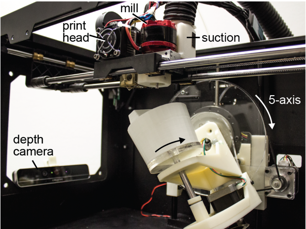
In this paper, we propose a different approach: instead of re-printing the entire object from scratch, we suggest patching the existing object to reflect the next design iteration. We built a system on top of a 3D printer that accomplishes this: Users mount the existing object into the 3D printer, then load both the original and the modified 3D model into our software, which in turn calculates how to patch the object. After identifying which parts to remove and what to add, our system locates the existing object in the printer using the system’s built-in 3D scanner. After calibrating the orientation, a mill first removes the outdated geometry, then a print head prints the new geometry in place.
Since only a fraction of the entire object is refabricated, our approach reduces material consumption and plastic waste (for our example objects by 82% and 93% respectively).
A collaboration between Hasso Plattner Institute and Cornell University.


ACM publication:
Alexander Teibrich, Stefanie Mueller, François Guimbretière, Robert Kovacs, Stefan Neubert, and Patrick Baudisch. 2015. Patching Physical Objects. In Proceedings of the 28th Annual ACM Symposium on User Interface Software & Technology (UIST '15). ACM, New York, NY, USA, 83-91. DOI: https://dx.doi.org/10.1145/2807442.2807467